

The wall-to-roof junction on a lean-to addition is the single most common entry point for water infiltration — and improper flashing there causes mold, rot, and structural damage that costs thousands to repair.
Most DIYers installing a lean-to addition or carport know they need flashing but get stuck choosing the right material, overlap dimensions, and installation sequence to satisfy both weatherproofing requirements and IRC code compliance.
Follow this guide and you will leave with a complete, code-compliant lean-to roof flashing installation — right material, right sequence, zero guesswork.
Why Lean-To Flashing Fails (and How to Prevent It)
Most lean-to roof flashing failures trace back to 3 installation errors — not material quality. Fixing them before you start costs nothing. Fixing them after water damage appears costs thousands.
Flashing Overlaps Are Too Short or Reversed
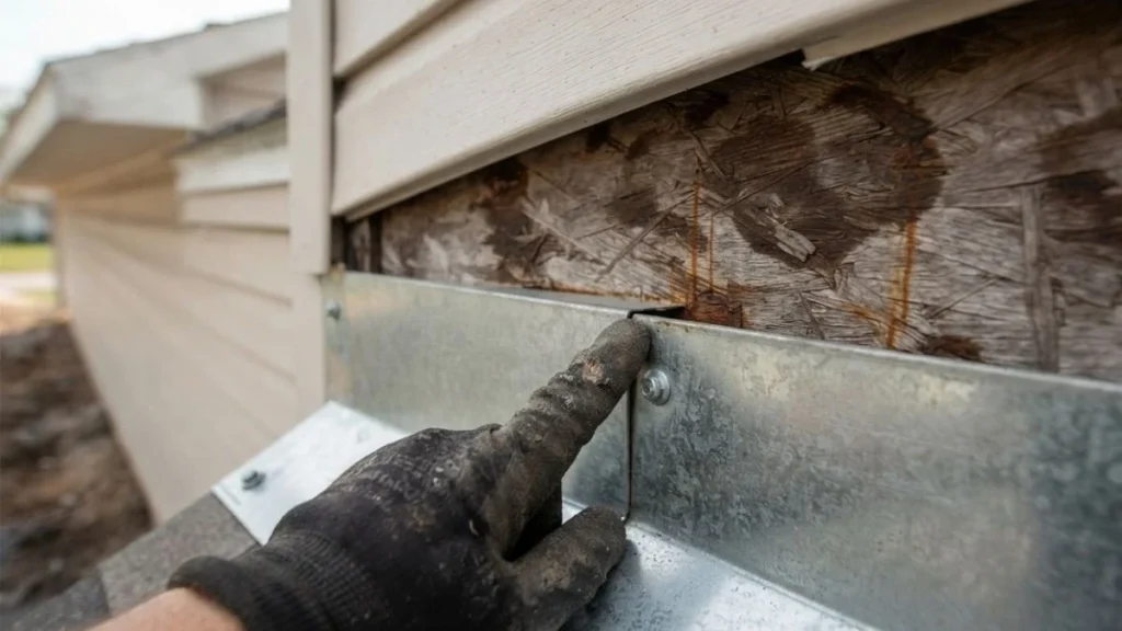
Water moves downhill and finds any gap. When headwall flashing installation leaves less than 4 inches of vertical coverage up the wall, or when a flashing piece is lapped in the wrong direction — lower piece over upper — water pools behind it. The roof-to-wall flashing detail must always shed water outward and downward, never toward the sheathing.
Siding Is Cut Too High Above the Roof Surface
Flashing under siding needs the siding trimmed to within 1 to 1.5 inches of the roof surface. Cut it higher, and you expose raw wall sheathing to direct rain. That sheathing absorbs moisture, swells, and rots — taking the ledger board with it in severe cases.
Fasteners Puncture the Flashing Face
Every screw or nail driven through the face of lean-to abutment flashing creates a direct water infiltration path. Fasteners belong at the top flange only, hidden under the overlapping siding or counterflashing above.
What the Building Code Actually Requires
IRC Section R903.2 mandates a continuous water-shedding barrier at every wall-roof abutment. That means no gaps, no exposed edges, and proper integration with the roof’s underlayment. Skipping this step is not just a leak risk — it is a code violation that can affect insurance claims and resale inspections.
Flashing Materials: Types, Gauges, and When to Use Each

Choosing the wrong flashing material for your lean-to roof connection is not just a durability problem — it can cause galvanic corrosion that destroys both the flashing and the fasteners within a few years.
Wall Flashing, Step Flashing, and Counterflashing
These three components work as a system, not individually. Step flashing integrates with each shingle course along a sloped roof-to-wall junction. Headwall flashing covers the horizontal connection at the top of the slope where the roof meets the wall directly. Counterflashing overlaps the top edge of the base flashing and is embedded into the wall — it prevents water from entering behind the entire assembly. All three must be sequenced correctly or the wall-to-roof flashing detail fails.
Gauge Comparison: 26 vs. 28
| Gauge | Thickness | Best Use | Trade-Off |
|---|---|---|---|
| 26 gauge metal flashing | ~0.0179 in | Metal roofs, high-wind regions | Higher cost, stiffer to bend |
| 28 gauge | ~0.0149 in | Standard residential lean-tos | Easier to form, less rigid |
For most DIY lean-to abutment flashing installs, 28 gauge works fine. Use 26 gauge when attaching to a metal roof or in coastal/high-wind areas.
Material Selection by Region
- Aluminum — lightweight, corrosion-resistant, best for most inland residential projects
- Galvanized steel — strong and affordable, but avoid contact with pressure-treated lumber without a barrier layer
- Copper — 50+ year lifespan, ideal for premium builds, incompatible with aluminum fasteners
Home centers like Home Depot stock standard aluminum and galvanized options. For 26 gauge steel or custom profiles, a local metal supplier will cut to length and save significant cost on larger lean-to projects.
Installation Sequence: From Wall Prep to Final Seal
Sequence matters more than any individual step here. Install flashing out of order and you will either trap moisture or create a gap you cannot seal without tearing the whole assembly apart.
Preparing the Wall and Siding Cutline
Calculate your cutline based on roof pitch and the required flashing overlap. The bottom edge of the siding must end 1 to 1.5 inches above the finished roof surface. Mark a level horizontal line across the wall at that height, score the siding with a circular saw set to siding depth only — never cut into the sheathing — then remove the lower siding courses cleanly. This exposes the wall sheathing for proper flashing under siding installation.
Positioning Flashing Behind and Over
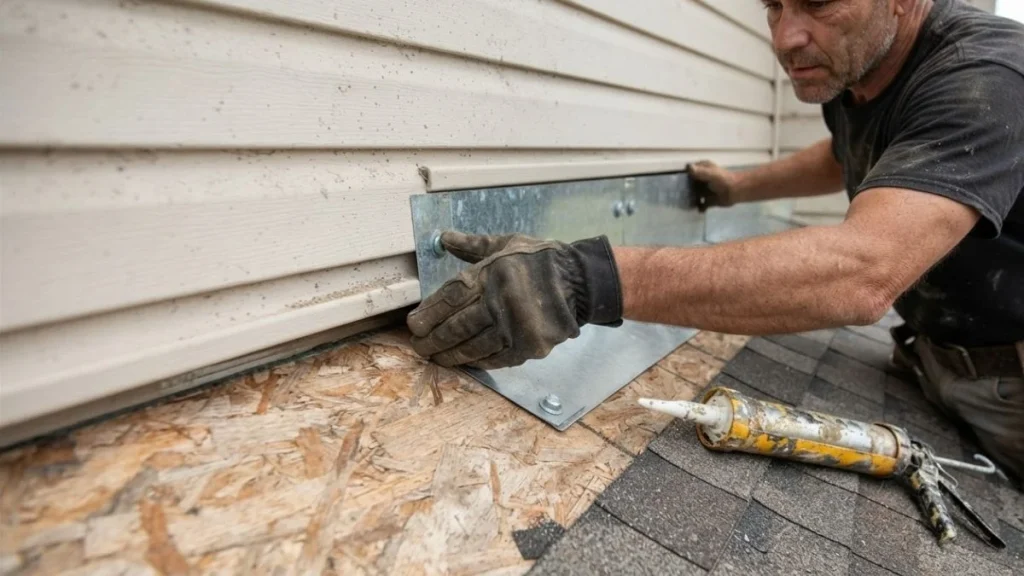
Slide the vertical leg of the headwall flashing behind the remaining siding above your cutline, with at least 4 inches of coverage up the wall face. The horizontal leg extends 6 to 8 inches onto the roof deck, running underneath the first course of shingles or metal roof trim above it. For step flashing along a sloped lean-to abutment, work bottom to top in 2 to 3 inch increments, integrating each piece with the shingle course beside it. Fasten 12 inches apart along the wall flange and 16 inches along the roof flange — never through the center face.
Sealing and Securing Connections
Apply a compatible elastomeric sealant — not standard silicone — under the flashing lip where it meets the wall and over each fastener head. Silicone does not bond reliably to painted surfaces and cracks with thermal movement. Use galvanized or stainless steel fasteners throughout; standard steel screws rust and back out within 2 to 3 seasons, breaking the seal at every fastener point.
Flashing to Existing Structures: The Add-On Challenge
Attaching a lean-to to an existing structure introduces variables that new construction does not have — existing finishes, hidden water paths, and surfaces you cannot modify without causing new damage.
Connecting to Standing Walls Without Roof Removal
Wall material determines your prep approach entirely.
- Wood siding — score and remove the lower course as described in section 4, then slide flashing behind the exposed sheathing
- Brick or masonry — cut a reglet (a narrow horizontal slot) into the mortar joint with an angle grinder, embed the flashing leg 1 inch deep, and seal with polyurethane sealant rated for masonry
- Metal panel walls — use butyl tape behind the flashing leg before fastening; do not rely on sealant alone against metal
When the lean-to roof pitch meets an existing eave, check whether the eave overhangs far enough to direct water clear of the new roof surface. If it does not, the headwall flashing installation must run up behind the existing soffit and tie into the wall above it — which sometimes requires partial soffit removal.
Stepped flashing transitions apply where a lean-to meets an existing roofline mid-span rather than at a flat wall. Each step piece overlaps the one below by 2 inches minimum, integrating with both the existing roof’s underlayment and the new lean-to roof connection.
Pole Barn and Carport Configurations
On a pole barn or open carport, the ledger board bolted to the existing structure becomes the primary flashing anchor. Flash directly over the ledger board flashing with the horizontal leg extending onto the new roof deck. For metal building walls, use self-drilling hex-head screws through predrilled holes — nails do not hold reliably in metal framing and create oversized puncture paths that bypass any rubber washer seal.
Common Installation Mistakes and Real-World Fixes
Most lean-to roof flashing callbacks — jobs that fail and need redoing — come from the same 5 mistakes. Recognizing them before you install saves the cost of a complete teardown.
Reversed Overlap Direction
This is the most damaging error and the hardest to spot visually once siding is back in place. When the upper flashing piece sits behind the lower one, water runs directly into the seam instead of over it. Every roof-to-wall flashing detail must follow the shingle principle: upper piece always overlaps lower piece on the weather-exposed face.
Siding Installed Too Low Over the Flashing Seam
Siding that covers the flashing lap point traps moisture between the siding and the wall. The bottom edge of the siding must remain 1 to 1.5 inches above the roof surface — visible, not buried. This gap also allows inspection without removal.
Caulk-Only Seals
Sealant fails. Elastomeric caulk typically lasts 3 to 5 years before UV exposure and thermal cycling cause cracking. Any wall flashing detail that depends entirely on caulk — with no mechanical overlap holding the water-shedding path — will leak within a single roofing lifespan. Caulk supplements mechanical overlap; it never replaces it.
Inadequate Fastening and Wind Uplift
Fasteners spaced wider than 12 inches along the wall flange allow flashing to lift under wind load, breaking the seal at the wall face. In high-wind zones, reduce spacing to 8 inches and use 1.5-inch galvanized roofing nails or stainless hex-head screws.
Assess Existing Damage Before Retrofitting
Before installing any retrofit lean-to abutment flashing, probe the ledger board and surrounding sheathing with a screwdriver. Soft spots indicate rot. Flash over compromised framing and you seal moisture in — accelerating structural damage rather than stopping it. Replace damaged framing first, always.
Which Flashing Method Works for Your Situation?
Your roof type, wall type, and whether you are retrofitting or building new determine the flashing method, material quantity, and code compliance path before you purchase a single piece of metal.
Decision Matrix: Matching Method to Condition
| Roof Type | Wall Type | Build Type | Recommended Method |
|---|---|---|---|
| Asphalt shingles | Wood siding | New build | Step flashing + headwall flashing, integrated with underlayment |
| Asphalt shingles | Masonry | Retrofit | Counterflashing set in reglet, polyurethane sealed |
| Metal roof | Metal wall panel | New build | Metal roof endwall trim + butyl tape, screwed through predrilled holes |
| Metal roof | Wood siding | Retrofit | 26 gauge metal flashing, slide behind siding, lap over metal trim |
| Flat/low slope | Any siding | New build | Continuous wall flashing with 6-inch roof extension + membrane overlap |
How Method Choice Affects Labor and Materials
Step flashing requires more pieces and more time than a single continuous headwall flashing run, but it handles roof pitch changes and siding integration better on sloped lean-to connections. A continuous counterflashing system over masonry adds reglet-cutting labor — typically 1 to 2 additional hours with an angle grinder — but delivers a cleaner, more durable wall-to-roof flashing detail.
When to Call a Professional
Four conditions warrant professional installation rather than DIY:
- Existing rot or structural damage in the ledger board or wall framing
- Masonry walls requiring reglet cutting and tuck-pointing
- Any situation requiring partial roof removal to access the wall tie-in point
- Complex multi-plane transitions where two or more roof pitches meet at a single lean-to abutment
Attempting these conditions without experience risks both building code compliance failure and accelerated structural damage from trapped moisture.
You May Read Also: How To Patch A Metal Roof
Ready to Seal Your Lean-To Connection
Mechanical overlap — not sealant — is what keeps a lean-to roof flashing system watertight for decades. Start your project by identifying your exact roof type, wall type, and build condition using the decision matrix in section 7, then pull the corresponding material list before touching a single piece of siding. If your probe test reveals soft framing anywhere along the ledger board, replace that wood before any flashing goes on.